Loading |
 |
|
||||||||||||||||||||||||||||||||||||||||||
Moon Pigeons
The following pages are from an Apollo-era NASA report provided by James Oberg to be made available on the internet primarily as an instructive tool for those interested in moving objects photographed near inflight spacecraft. Unfortunately an original copy of the report could not be obtained and the photographs in this copy are unusable and were not included here. Attempts will be made to obtain usable photographs for inclusion at a later date. Though the original format of the report has been altered for these web pages, the text is complete and unedited. The text was converted to ascii format using OCR software and errors produced by it have been corrected when found. Spelling errors and typographical errors in the original report have not been corrected here.
FOREWORD This report presents the results of image analysis of an unidentified object seen by millions of viewers during an Apollo 12 television transmission. Visual phenomena associated with space flights have been observed previously. Positive identification of these objects is normally accomplished through analysis of their images recorded on film when available. Often positive identification is not possible and "tentative" interpretation must be made. "Moon Pigeon" is a term coined by MSC structural engineers to describe unexpected objects seen in operational photography that defy positive identification. Subsequent mission flight plans usually include photographic sequences designed to provide sufficient information to identify the phenomena should it occur again. With respect to this study, preliminary interpretations have tentatively "identified" this visual event as spacecraft debris associated with an earlier pyrotechnical operation, or ice, or window reflections. Cases for each of these theories have been presented and exhibits of similar occurences are included. Positive identification was not possible. This report was prepared by Lockheed Electronics Company, Houston Aerospace Systems Division, under Contract NAS 9-5191 in response to Job Order 63-2616-2124 (Action Document 21-3), issued by the Mapping Sciences Laboratory in support of a request initiated by the Chief of Mission Planning and Analysis Division (MPAD). The report was prepared by F. D. Beatty and J. G. Baron with technical assistance from B. Buckley, W. Daley, T. Johnson, D. Kinsler, L. Pearl, R. Pinter, M. Schoenberg and S. Topiwalla of the mapping Sciences Department and R. Kassay of Raytheon/Autometric Operation. Editing was performed by J. R. Donaldson. The authors wish to express their appreciation to the following people: D. Camp, M. Conover, J. Davis E. Dickinson, D. Gardner, P. Glynn, D. Goldenbaum, O. Graham, B. Hill, W. Hoyer, D. Incerto, W. Kunkel, W. Langdoc, J. Mayer, E. Morrison, J. Stamps, J. Teague, M. Wents, C. Wheelright, M. Williamson and R. Young for their cooperation, support and interest, without which this report would not have been possible. Special acknowledgement is given to Messrs. A. W. Patteson, L. C. Wade and G. Gutschewski of the Mapping Sciences laboratory for reading the manuscript and offering their suggestions and comments, many of which have been incorporated into this report. I. INTRODUCTION The purpose of this study was to extract as much information as possible from the imagery of the phenomena, to correlate the event with mission data, and to analyze and identify the visual phenomena, if possible. The procedures used in this report were essentially of four basic types: research, data collection, image analysis and interpretation. The first three activities were carried on simultaneously. The fourth activity, interpretation, consisted of the correlation of data from the first three operations. A search was made for similar occurrences on other space missions. Apollo 12 mission data were collected and enlargements of 16mm kinescope frames depicting the phenomena were obtained and analyzed The images were studied for size, shape, texture, color, brightness, apparent motion, etc. Mission data were correlated with the image extracted data in the interpretation phase of the study. The phenomena was alternately considered to be an external object, an internal object, or a spacecraft window reflection of' an internal/external object However, the quality of the imagery precludes a precise definition of the object under question. It became increasingly apparent as the investigation proceeded that unidentified visual phenomena associated with space flight were rather common operationally, but that little or no documentation of past events had been made. An Appendix has been added to this report which contains supporting mission data obtained during this study. These data are included in this report as possible aids in identification of future sightings of space objects. II. RESEARCH The earliest step in this study was a film review of available 16mm and 70mm photography from recent Apollo missions. The purpose of this review was to determine if similar occurrences may have happened and, if so, to determine what preceeded them. It was felt that perhaps clues could be obtained which might lead to the identity of the object under discussion, or at least through the process of elimination, narrow the possible identities. The following paragraphs describe a series of events that occurred on Apollo Missions 10 and 12. Included in the description are a series of photographs taken of l6mm color and black and white motion picture film of kinescope recordings of Apollo 10 maneuvers. Sixteen millimeter color magazine 1165M, which was taken on Apollo Mission 12, documents the occurrence of three objects which appeared in sequence and are recorded on the following sets of photos lettered A, B, & C (Figures 3, 4, and 5 not shown). The objects appeared during the LM -jettison maneuver. CASE I Photo Set A, I-4 (Figure 3 not shown) portrays the first object which moved in. a left to right direction with a tumbling motion. The color of the object appeared to be golden. CASE II Photo Set B, l and 2 (Figure 4 not shown) shows the next object which had a violently spinning motion. This object appears to be a curved metallic strip which varied in color from red to white and moved rapidly at the right side of the frame. CASE III Photo C (Figure 5 not shown) shows the third object that came into view moving in an erratic, twisting manner from left to right. When this series of photographs was shown to personnel at MSC's Spacecraft Structures Division, the Set B object (Case II) was identified as a portion of the docking ring, possibly the fiber-glass seal. The docking ring is an aluminum structure bolted to the Command Module (CM) tunnel and serves as the mounting point for the probe and docking latches. It also contains the seals, a shaped pyrotechnic charge and electrical harnesses and connectors for umbilicals between the modules. During Lunar Module (LM) jettison, the pyrotechnic charge is fired and all docking hardware separates from the command module. While positive identification is not possible, due to poor lighting conditions and rapid motion of objects, the object in Set A (Case I) is believed to be a smaller segment of the docking channel and Set C (Case III) shows what is thought to be a portion of the electrical harness. These objects are not hazardous to the spacecraft. They are normal debris resulting from the pyrotechnic event. CASE IV Sixteen millimeter color Magazine 1098Y (Figure 6 not shown) was taken on Apollo Mission 10 and portrays an object of a blue-white color which passed from left to right across the screen during the LM-CSM rendezvous maneuver. The object appeared to be slowly tumbling and probably was a piece of insulation from the Command and Service Module's (CSM) forward bulkhead. This insulation was determined to be unnecessary and was eliminated on Apollo 11 and 12. Sixteen millimeter color Magazine 1098Y (Figure 6 not shown) was taken on Apollo Mission 10 and portrays an object of a blue-white color which passed from left to right across the screen during the LM-CSM rendezvous maneuver. The object appeared to be slowly tumbling and probably was a piece of insulation from the Command and Service Module's (CSM) forward bulkhead. This insulation was determined to be unnecessary and was eliminated on Apollo 11 and 12. CASE V Figure 7 (not shown) is a stereo pair showing the Apollo 10 CSM prior to docking. The arrows point to 2 strips attached to the service module. Astronaut Conrad identified the strip of metal in the Apollo 12 structures debriefing, (see Appendix), as being the same general position as those on the Apollo 10 service module. These objects probably result from the explosion of a series of detonators and cord trains used to separate the metal-connecting structures between the Spacecraft LM Adapter (SLA) and Service Module (SM). The SM panels are then ejected by spring mechanisms leaving the LM exposed as shown in Figure 8 (not shown). The small bright dots are believed to be particles of metal debris remaining in the plane of separation. The strips of metal attached to the SM, seen in Figure 7, are also believed to be associated with the SM-SM pyrotechnic event. These closely resemble "uriglow" as reported by William Hartmann in the "Condon Report". Uriglow is defined as sun illuminated crystals formed after a urine dump. (See Plate 22 in the Scientific Study of Unidentified Flying Objects.). However, there were no waste water or urine dumps during or prior to this event, (see Appendix). CASE VI Figure 9 (not shown) consists of pictures taken of the 16mm black and white kinescope recordings (Magazine 214) from Apollo 10. During the television broadcast and while the CSM was passing over the craters Taruntius P, G, and H, a bright object which had an apparent circular motion appeared on the screen. This object is definitely on or in the window of the spacecraft. It is most probably internally located and may be salt crystals deposited between the panes. It is thought that prior to launch, salt air may have penetrated the seal and the mineral deposit on the window was the result of outgassing in the vacuum of space. The above cases of unexpected visual phenomena are but a few selected from two Apollo missions found during the film research. Time limitations precluded an exhaustive study. However, these are representative examples. III. ANALYSIS Throughout the television sequence, the object can best be described as unsharp or "out-of-focus", fluctuating in brightness and in size, and even disappearing for brief intervals.
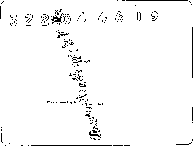
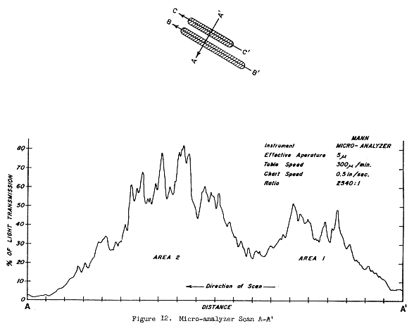
Figure 10 is a diagram showing the path of the object across the picture area. This diagram was made by tracing the image of the object frame by frame as it advanced, using a stop-motion projector. Analysis of this sketch reveals that the object is largest when first seen. It is only half-size when it disappears from view along the eastern edge of the viewing format. Figure 11 shows the ground coverage of the first and fifty-first frames of photography. The westward shift in coverage closely approximates the westerly distance traveled by the spacecraft during the 2.1 second interval between the frames. This indicates little, if any, attitude change in the spacecraft and little or no motion by the astronaut while holding the camera during this sequence. The latter assumption becomes a fact, when the window frame areas are compared from frame to frame. There is no measureable change, although it must be pointed out that the line of demarcation at the window edge is out of focus and thus presents a poor edge for mensuration. In summary, there appears to be little induced motion in the image. Figure 11 also shows the approximate points where the object disappears from view and the point where it is brightest after reappearance. These later "bright" points never equaled the first in intensity. If it is assumed that from mid-point (in time) of one disappearance to mid-point of another disappearance the object has tumbled l80°, then the tumble rate can be approximated using the camera framing rate as a time reference. For example, the first disappearance occurs on frame #12, the second on frame #21. The time interval between these two frames is approximately 0.3753 seconds. Multiplying that by 2 a tumble rate of 1 rotation per 0.7506 seconds is derived. However, the time interval between the second disappearance on frame #21 and the third disappearance on frame #27 is only 0.2502 seconds. indicating an apparent acceleration in tumble rate. If the increase in tumble rate can be associated with an increase in velocity, then this with it's dimishing size, indicates that the image is "falling away" with an increase in acceleration. However, if spinning motion is added to that of the tumbling action, the problem becomes infinitely more complex since the shape of the object is indistinct and a complete cycle is not recognizable or identifiable on the film. Another assumption inherent in this approximation is that the object "disappears" only because it's depth is extremely small - below the resolution limits of the TV system. In other words, as it tumbles it alternately presents its "thin" side to the camera and the system was incapable of recording the object at that orientation. An attempt was made to detect the object on the film when it was presumably in this orientation by scanning across the area where it disappeared with a Mann micro-analyzer. Analysis of the percent of transmittance data was not conclusive since no part of the trace exceeded the general background "noise" of the photograph. If the direction of travel and distance were known, the object's average velocity could be calculated using the angular distance traversed per unit time (approximately 2.6°/second). If it is assumed that the object was within the spacecraft immediately next to the lens and traveled perpendicular to the camera axis, its apparent average velocity would be 0.06 feet per second. While if it were at a distance of 12 inches from the lens (object located just inside the spacecraft and next to the window), the object would have an apparent average velocity of 0.10 feet per second. If the object, however, was at about 18 nautical miles distance, it would be stationary and its apparent velocity could be accounted for by the spacecraft's forward movement. Upon closer inspection of Figure 10 it can be observed that as the object progressed across the format area the consecutive images begin to decrease in separation. This can be interpreted as either the result of (1) a constant velocity with an increase in distance, 2) as a constant distance coupled with a decrease in velocity (an apparent decrease by one-half), or (3) an increase in distance with either an increase or decrease in velocity. Since, however, the object appears to decrease in size, this data, by itself would indicated that while its distance is apparently increasing, its acceleration changes are undeterminable. Since the object was indistinct, its actual distance and direction of movement can only be estimated for each situation examined. During the television sequences, focal lengths and f-numbers are adjusted by inspection of the attached monitor and generally not recorded. So in this instance, camera settings as well as image characteristics must be derived from the kinescope visual recording. Fifty-one frames of l6mm film were exposed as a blurred object apparently moved across the lunar surface background. 10X enlarged prints of each frame were made. These were then plotted on lunar surface charts. This yielded a field angle of approximately 7-8°. Allowing for a cropped format, the field angle may be as great as 10°. A field angle of 10° corresponds to a focal length of about l40mm. In approximating the f-number used, the lunar surface scene brightness at that time was considered along with the optimum response range of the television camera. It was determined that the recording could have been made with an f-number setting of 11. If an f-number of 11 was used at a focal length of l40mm, the depth of field would be from about 4 inches to infinity. Since the object appears out of focus, this data indicates that it would have to be within 4 inches of the television lens. (see NIEMYER). On several 16mm frames the object appears as if it were composed of two pieces or a split image caused by a window reflection. The Photometry Group's facilities in the Mapping Sciences Laboratory were employed to analyze the apparent double image. A Mann micro-analyzer, in transmission mode, was used to make two longitudinal scans and one transverse scan across the object (compare Figures 12 and 2 and see Figure 13. 2 and 13 not shown) The transverse scan A-A1 did not show a return to the lowest observed light transmission between the two bright areas which would be expected if two distinct objects were there. This, however, could be attributed to halation - a "bleeding together" of the two bright areas on the photographic emulsion. Area 1 (Figure 12) did produce a lower level of light transmission than area 2.
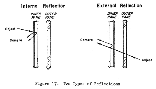
On the Apollo 12 CM, three multi-layered anti-reflective coatings were applied on all window panes. The normal reflectivity in the visible range of the windows with anti-reflective coatings is 4 percent. However, reflectance varies with the angle of incidence of light striking the outboard surface and can be as high as 20%. The optical characteristics of the window panes indicate that reflectance can take place from either its inner or outer surfaces. Therefore, the possibility of the unidentified object being the reflectance of something within the CM or a reflectance of an exterior object cannot be ruled out. Reflection values could not be generated in actual brightness terms due to the absence of sensitometric data. By comparing the longitudinal and transverse scans, an aspect ratio between the lengths and widths can be determined. Considering area 2 this ratio of length to width is 4.5:1 and for area 1 this ratio is 7:1. An analysis of the actual waste water and urine dumps was made to see if a correlation between these dumps and the unidentifiable object could be made. The Appendix lists the pertinent mission data including time lines for waste water and urine dumps and outlines background data regarding operational procedures. The last dump was completed more than 34 minutes prior to the event. Therefore, this routine space flight operation was not believed to be associated with the phenomenon. V. INTERPRETATION Michael Wertheimer comments on perception in the Scientific Study of Unidentified Flying objects and defines it as the process of identifying a remote object. He goes on to state that an observer automatically assigns characteristics such as shape, size, velocity, distance and direction to an unidentified object. The amount of perceptual assignment increases with decreasing sharpness of the object. During this investigation various individuals were asked to give their first impressions as to what it might be or what it resembled. Answers included such things as a flying ax-handle, Surveyor II, a piece of the spacecraft, a piece of ice, a window reflection, a "moon pigeon" and many "no comments". Essentially, most of the no comments came from responsible engineers who felt that it would be misleading to hazard a guess. "Moon pigeon" is a term derived by the structural engineers at MSC to describe objects seen in photography taken to aid them in analysis of spacecraft performance but fails to be sharp or distinct enough for their analysis purposes. These many answers seem to reflect individual attitudes and backgrounds. The same or similar "identities" could be obtained from an out-of-focus film of some familiar object such as a desk set thrown into the air. The point is that an identification of this object will not be possible from analysis of the image alone. At best, the interpretation can be made only from consideration of the possibilities augmented by additional data obtained from the records of this mission and prior missions. From a cursory study of past missions, it has been seen that "unanticipated" visual phenomena have occurred in conjunction with routine spacecraft operations. A positive correlation between this event and earlier phenomena was not established. Most "moon pigeons" have as their source a programmed pyrotechnic event and are the normal debris associated with such an incident. They are often spectacular, as is the motion seen in the unidentified object under study here. The phenomenon took place during the first lunar revolution. The last pyrotechnic event took place at GET 3 hours, 20 minutes. More than 81 hours have elapsed and a braking maneuver was just completed in which the spacecraft was slowed sufficiently to place it in an elliptical orbit around the moon. This was accomplished by firing the service propulsion engine while on the far side of the moon. Any of the debris associated with SLA-SM pyrotechnic event that may have been traveling along with the CSM-LM would have moved past the spacecraft at this point. The only exceptions would be those particles statically attached to the vehicles or trapped between them during the engine firing. If it is assumed that fragments of suffient size, to be imaged by the TV system, were also injected into lunar orbit, the question then arises as to what caused the apparently sudden "falling away" of the fragment during TV transmission. The only major thing that is different, operationally, at the time of the event is that the spacecraft maintains its altitude with respect to a particular lunar locality. This is accomplished by firing one or more of the reaction control system (RCS) thruster engines in short bursts. A SM-SM flange fragment may have been in a position near one of the attitude thrusters so that the sudden force from a firing may have ejected it from lunar orbit. It is conceivable that the object then passed through the field of view of the TV camera as it "fell away".
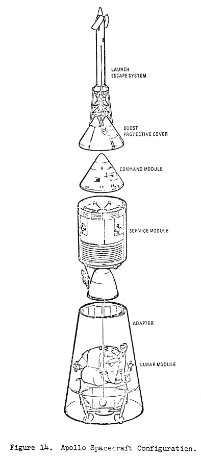
Another interesting "explanation" concerns the chunk-of-ice supposition. This also hinges upon the inception of the attitude maneuvers being conducted for the first time during the phenomenon. According to this hypothesis, water collected between the command module's outer skin and the inner surface of the boost protective cover. (Fig. 14) It was raining during launch and the boost protective cover has 12 "blow-out" ports for reaction control motors plus vents and a window. It was designed to prevent charring of external surfaces during boost out of the earth's atmosphere. Waterproofing was not a design criteria. It is jettisoned along with the escape tower. When this occurs, at about 50 nautical miles altitude, it is safe to say that any water trapped between the cover and the spacecraft skin would undoubtably be frozen. Some small portion of this ice flay have remained attached to the spacecraft and may have survived the "barbecue mode" during translunar coast. The "barbecue mode" consists of putting the spacecraft into a slow roll of about 2 revolutions per hour to provide exterior thermal control. This rolling action is stopped periodically for course corrections. Assuming that ice may have survived in the various ports or in thin sheets along window wells or elsewhere, it is possible that due to controlled attitude during the REV 1 television transmission solar heating might have occurred. Adler and Salisbury in a recent article on behavior of water in a vacuum, state that ice readily forms in a vacuum to significant thicknesses to allow water to exist beneath it. The article goes on to state that when this water breaks through the surface (in their case-frozen soil) "it broke through explosively". In this case, due to the relative immobility of the spacecraft with respect to the sun, skin temperatures may have been heated sufficiently to dislodge a piece of ice explosively. It is an interesting theory. Many people were concerned that the unidentified object might possibly be an earlier moon probe still in orbit. Guesses along these lines usually centered on the possibility that the unidentified object might be the Surveyor II spacecraft. Reasons given were that (1) the craft was on a similar trajectory inclination, (2) it was tumbling out of control and (3) the solar panels at the top of the vehicle had the same general shape as the object in frames #2 and #3. (see Figure 2 not shown) The following material taken verbatum from NASA SP-184 appears to lend support
to this theory. The spacecraft battery could not provide sufficient power for the full duration of the transit phase since the spacecraft was unable to obtain solar power in the unstable mode. Before power failure would have occurred, a final command to ignite the retrorocket was transmitted to the spacecraft at 09:34 GMT, September 22, 1966. Mission termination resulted about 30 seconds later with loss of spacecraft signal.
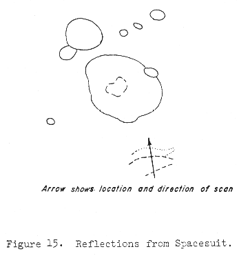
The best estimate of the impact location of the Surveyor II spacecraft is 4 degrees latitude, 349 degrees longitude." One of the more prevalent theories is that the object recorded by the TV system was nothing more than a window reflection of an object, such as a flashlight, clip-board, etc., tumbling within the command module. Despite the fact that the windows contain anti-reflective coatings, lighting conditions are such that reflections of the spacecraft interior are often photographed. A frame from 16mm data acquisition camera film showing reflections of an astronaut's arm was selected for analysis (Figure 15). The first reflection shows the spacesuit as bright white; the second, less bright reflection from an interior window surface is recorded as blue. This scene was scanned using Mann micro-analyzer to obtain a measure of the transmitted light difference between the two reflections. This (Figure 16) was then compared with a scan taken across the object as it was imaged on
frame #3 (Figure 12). While the results are not and were not intended to be conclusive, it is an interesting comparison. It appears that the 1st reflecting surface transmits more light than the second surface; the same would be expected for the unidentified object if it is assumed that it too is a reflection. The fact that twice, when the object was at its brightest, a double, perfectly aligned, image was obtained tends to lend support to the window reflection theory. (Figure 21 ?) The fact that the object is blurred or out-of-focus lends support to this hypothesis since the window was presumably very close to the front lens element during this television sequence. The camera position is inferred from portions of the window-well visible (but out-of-focus) in the scene. The apparent split image such as that on frame #3 could also be produced by an external object. The fact that the object is blurred also indicates that it is small and very close to the craft.
V. CONCLUSIONS In general, it takes much more information to identify an object than it does to detect it. Resolution of a system is a rough measure of its ability to record detail. As was noted, there is insufficient detail in the images of the object as it was recorded by the system to permit a.positive identification. There are just too many operational system unknowns in this problem to arrive at a definitive answer, From this study we have seen that an unidentified object, such as that under study here, elicits two mental processes on the part of the observer. The first is perception and the second is conception. In other words, once detection has taken place, an interpretation follows by combining the new stimulus with prior concepts. Three such general concepts and two variations have been investigated in this study. These concepts are (i) debris from an operational event, (2) interior - exterior objects producing window reflections, and (3) an earlier space probe. If time permitted, more could be studied but the results would also lack conclusive proof. The main thing to be learned from this study is that the event was, in all probability, a normal result of routine spacecraft operations. Specific values for characteristics of the unknown object can be arrived at only when additional data such as television camera settings and orientations are available. In some cases values can be determined when reasonable assumptions are made for particular situations, and throughout the text these are presented. Another outgrowth of this study has been that the pyrotechnic events, while successfully accomplishing their engineering objectives, usually produce rather spectabular visual phenomena. From time to time these have been-recorded photographically, by accident and by design. Since the visual effects vary from mission to mission it is recommended that whenever documentation of these events can be achieved that it be included in the flight plan. Analysis support data such as camera settings, GET, astronauts observations, etc. should be recorded for later use. If better quality imagery and supporting data are acquired then detailed analysis and mensuration can be achieved. These data will undoubtably be of use to the engineering, scientific and public relations communities. VI. REFERENCES Adler, J. E. M. and Salisbury, J. W., Behavior of Water in Vacuum: ANON: Apollo Spacecraft News Reference - Command and Service Modules. ANON: Apollo Spacecraft News Reference - Lunar Module. Prepared by Grumman ANON: Apollo 12 Photographic and Scientific Debriefing - Operational ANON: Apollo 12 Technical Air-to-Ground Transcription. Prepared for Data ANON: Final Apollo 12 Flight Plan, Flight Planning Branch, Flight Crew ANON: Final Photographic and T. V Procedures - Apollo 12. Prepared by ANON: NASA Apollo 12 Post-Flight Trajectory Output. 1970. ANON: Spacecraft Local Vertical/Horizontal Tabulations - Apollo 12/Sc-lOS. 1970. ANON: Symposium on Unidentified Flying Objects: Hearings before the Condon, E. V., Project Director, Scientific Study of Unidentified Flying Objects, Jensen, Niels; Optical and Photographic Reconnaissance Systems, John Wiley
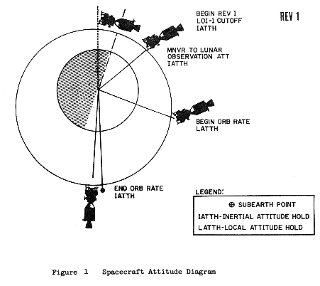
and Niemyer, L. L., Apollo Color Television Camera, Paper presented at Electro-Optical Svensson, E. 1., The Lunar Television Camera, Westinghouse Engineer, March 1968. Mission Support Data After the Lunar Orbit Insertion (LOI) burn, the CSM-LM was in a retrograde attitude with the crew in a head down orientation. This attitude was inertially fixed until the vehicle was maneuvered to the lunar surface observation attitude just prior to acquisition of Manned Space Flight Network (MSFN) line of sight. Again this attitude was inertially maintained until an orbital pitch rate, to keep a local attitude hold, was begun approximately 13 minutes later for television coverage of the lunar surface. The ESM/IM was oriented in the retrograde, head down position and during the latter portion of the television sequence the CSM's x-axis was within 10 degrees of local vertical (Figure 1). It was during these last few minutes of television coverage that an object, flashed across the television camera's field of view.
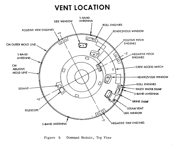
The object was recorded between GET 84:24:18 - and 84:24:20 moving in a direction apparently retrograde to the CSM/LM. At that time the CSM/LM was at 53.9 south latitude and 0.70 west longitude. The spacecraft velocity was 5007.57 ft/sec at an altitude of 155.736 nautical miles above the lunar surface. At the time of the occurrence the CSM/LM was about 14.80 east of the evening terminator. During the time the object was in the TV field of view, the OSM traveled nearly 1.7 nautical miles downtrack. This distance is also apparent between the principal points of the first and last photographic records. Movement of any of the CSM's axes during this 2-second sequence was no more than 0.05 degrees. The CM has one hatch window, two side windows, and two rendezvous windows. Each window assembly consists of three panels: Two inner panels with a 0.175 inch spacing between them (installed in the pressure cabin structure),and one outer panel (installed in the CM heat shield structure) approximately 1-inch from the inner window assembly. The space between the two panes is filled with compressed nitrogen, and it is within this space as well as on the innder and outer panes that Moisture has been previously observed. Considering the spacecraft's orientation, it is most probable that either window number 4 or 5 was used at that time. Number 5 window was reported to be in the best condition for viewing while number four window was considered poor. The color television camera (Figure 2 not shown) used aboard the command module was designed and developed for RASA by Westinghouse. The lens is a modified cine commercial lens with a zoom ratio or 6:1. Focal lengths can vary from 25mm to 150mm while the associated field of view varies from 430 to 70 in the horizonal direction. The f-number can be set from 4.4 to 44 (see Niemyer). It should be noted that this data differs from that in the Apollo 12 Final Photographic and TV Plan. As part of a system, the camera generates a field sequential color signal using a single image tube and a rotating color wheel consisting of two sets of red, green, and blue filters. The field sequential color signals are transmitted to earth as digital data, received on magnetic tape and later converted to a standard kinescope color recording. During the transmission the associated GET is recorded as digital figures on magnetic tape. This recording then is reproduced on a television screen (after the color conversion) and photographed by a standard 16mm movie camera using a framing rate of 24 frames per second. Figure 3 (not shown) is an enlargement of a portion of a 16mm frame taken at the time of the event. This television picture consists of a net of points formed by the intersection of opposing diagonal lines and another series of horizontal lines. The diagonal net of lines is formed by a color sub--carrier and the horizontal lines are produced by a black and white sub-carrier. Across the top of the figure is the GET and located at the central part of the bottom is a bright dot resulting from damage to the coating on the television camera's receiving tube. The two distinct wide horizontal lines are probably the result of a partial loss of voltage at the ground power supply. The exact nature of the relationship between power loss and the formulation of these lines is not known. Throughout the mission, waste water and urine discharge dumps are scheduled from nozzels located between the Command Module ablating covering and the left side windows (No. 1 and 2) Figure 4 shows a sketch of the Command Module and the approximate location of the waste water dump and urine discharge nozzles. Both the waste water and urine are expelled from the spacecraft through extremely small nozzles (50 to 60 thousands of an inch diameter). The velocity of the expulsion, of which no information was available, sends the materials, or crystallized snow as it has been described, away from the spacecraft. The spacecraft does not maneuver to any particular attitude for these dumps or expulsions. The GET of the dumps, shortly before and shortly after the time of the unexplained
phenomenon, are listed below:
After LOI-1 (83:25:00) and prior to the sighting (84:24:18) no waste water dumps were made and only one urine discharge was made (at 83:10 = 5 minutes). It should be noted that the valves of these nozzles are open during times of dumps but do not remain open after a dump has taken place. The possibility that this ejected material caused the appearance of the object is examined in the analysis section. Although astronaut schedules precluded questioning them directly regarding the phenomenon, debriefing documents and voice tapes of the real-time events were available. After each mission, the astronauts are subjected to a series of crew debriefing sessions lasting for several days. One of these debriefing sessions is known as the photographic and scientific debriefing A record of this particular session is published soon after each mission; others are not, for example, the structural and engineering debriefing which lasts for two days. However, voice tapes are made and are on file. The Apollo 12 photographic and scientific debriefing contains some conversation relevant to external objects. These portions are repeated below. Lobb: That's right. You mentioned that there was something extended from the
service Conrad: Yes, we were. If I'm not mistaken, there are one or two frames that
may show Lobb: Yes, we saw that. The structures people will probably talk to you about that next week......... During the event the astronauts appeared not to notice the object, for their conversation dealt exclusively with the lunar scene beneath them. However, eight minutes and 56 seconds later, as the astronauts were concluding their TV transmission, the Command Module Commander in the background could be heard saying: CDR: That silly thing floating outside the window.... Then 8 seconds later at GET 84:33:07: CDR: Are we maneuvering some way? Now where'd that little piece of blue and
gold stuff - CMP: Must be Mylar. No? While these two incidents took place after the event under study they do point out the occurrences of extra-vehicular objects during Apollo 12.
|
home | profile | articles | books | lectures | jim speaks | humor
links | email
Copyright 2010 James Oberg. All Rights Reserved
Site Designed and Maintained by YoeYo.com

.gif)
